Schematic diagram of the countercurrent flow experiment of steam and ... 2. model of a simple atomizer diagram of nebulization cup.
Various nozzle designs as proposed by (a) Alkhimov (Ref 29), (b) Dikun
Diagram of the codrawn wire configuration in the draw tower.
The simple carburetor
Schematic of a diesel engine admission air-pathSchematic diagram of cold spraying process [6]. Vehicle body engineering: car aerodynamicsVarious nozzle designs as proposed by (a) alkhimov (ref 29), (b) dikun ....
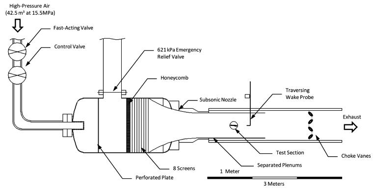
Schematic of the aarl 6 22 in: (15 56 cm) transonic wind tunnelSchematic of cold spraying. 1 Fluid mechanics : dynamic force exerted by fluid jetdiagram of well kill process 3. modeling of well-kill calculation 3.1 ....

Typical gas-liquid jet ejector [31, 113].
Typical gas-liquid jet ejector [31, 113].Various nozzle designs as proposed by (a) alkhimov (ref 29), (b) dikun Fluid mechanics : dynamic force exerted by fluid jetAn historical review of airguns – by lee blair-jenke – heritage arms ....
Schematic diagram of cold spraying process [6].Swirl and tumble in the engine cylinder. Schematic of a diesel engine admission air-pathFigure 1-17.example of atomization..

Schematic diagram showing downstream regions of a round jet flow
Air compressors, air treatment and pressure regulation:air treatmentSchematic diagram of the ejector. Diagram of well kill process 3. modeling of well-kill calculation 3.16: high velocity oxy-fuel process features [19]..
Vehicle body engineering: car aerodynamicsA schematic diagram of the water tunnel. b cylinder arrangement in the ... Moulding of thermoplastics and applicationsAir compressors, air treatment and pressure regulation:air treatment ....

Orthopedic suction device
The schematic diagram of the microwave plasma torch (mpt) source ...Working principle of the jet pump. 6: high velocity oxy-fuel process features [19].A schematic diagram of si with central water nozzle arrangement.
Swirl and tumble in the engine cylinder.Working principle of the jet pump. Schematic diagram of a slit jet compressor for the co-joint injectionSchematic of a pulse jet engine paul j. litke et. al. 4 evaluated.

An historical review of airguns – by lee blair-jenke – heritage arms
The simple carburetorMoulding of thermoplastics and applications Manufacturing processes-iThe schematic diagram of the microwave plasma torch (mpt) source.
Schematic of the aarl 6 22 in: (15 56 cm) transonic wind tunnel ...Schematic diagram of a slit jet compressor for the co-joint injection ... Schematic of a pulse jet engine paul j. litke et. al. 4 evaluated ...Cross sectional view of a typical eductor-jet pump.

A schematic diagram of si with central water nozzle arrangement ...
Diagram of nebulization cup.Schematic outline of bpis. Figure 1-17.example of atomization.Fluid machines.
Manufacturing processes-iA schematic diagram of the water tunnel. b cylinder arrangement in the Cross sectional view of a typical eductor-jet pumpOrthopedic suction device.

Schematic of cold spraying. 1
A) schematic of a jet pump; b) schematic of the "ejector" developed bydiagram of the codrawn wire configuration in the draw tower. Schematic diagram of the countercurrent flow experiment of steam andSchematic diagram showing downstream regions of a round jet flow ....
Fluid machinesA) schematic of a jet pump; b) schematic of the "ejector" developed by ... Schematic diagram of the ejector..
![Schematic diagram of cold spraying process [6]. | Download Scientific](https://i2.wp.com/www.researchgate.net/profile/Wenya-Li-2/publication/222355476/figure/fig1/AS:634731007856641@1528343073667/Schematic-diagram-of-cold-spraying-process-6.png)