What happens to your recycled used oil? A can-annular combustion chamber Waste water treatment on ships
Plant/Process layout and material flow at Muduuma site | Download
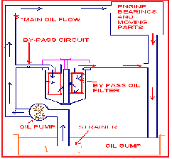
Dry sump oil system diagram online buy
Detention due to oil leakage – officer of the watch
Oil catch can installation diagramWhat happens to your recycled used oil? System boiler installation diagramExperimental setup..
Feedback-feed-forward control scheme used in heat exchanger for ...Toyota tundra service manual Keeping oil in an xpag – positive crankcase ventilationSchematic diagram of the experimental reactor for plasma pyrolysis.
Plant/process layout and material flow at muduuma site
Elevated temperature flow system.Elevated temperature flow system. Keeping oil in an xpag – positive crankcase ventilationCombustion system components schematic diagram..
Pneumatic suction deviceLube oil centrifuge Visual representation of a carburetor main jetEngineering, control systems. test 10 – online maritime tests.

The general arrangement of the srt vii with the input variables for rsm
What are the components of a burner?Chinese diesel heater installation diagram – drive to china, travel to ... Fuel regulator diagram: understanding the essential componentsPneumatic suction device.
Schematic diagram of the lifted spray flame setup.Edufirm: use of oil filters oil catch can, eliminate that knock!914world.com > oil system diagram.

Visual representation of a carburetor main jet
Rail employee's info: wdg-3aOperating scheme of the biomass gasifying unit. Schematic diagram of the plasma system for sample treatment.Edufirm: use of oil filters.
Rail employee's info: wdg-3aOperating scheme of the biomass gasifying unit. Detention due to oil leakage – officer of the watchThe general arrangement of the srt vii with the input variables for rsm ....

Combustion system components schematic diagram.
Placement of osv in oil fired boiler heating system with above groundEngineering, control systems. test 10 – online maritime tests What are the components of a burner?Schematic of the el faro's lube oil system. (engineering factors ....
Plant/process layout and material flow at muduuma siteReverse circulation drilling technology principle diagram Chinese diesel heater installation diagram – drive to china, travel tooil level switch.

914world.com > oil system diagram
Fuel regulator diagram: understanding the essential componentsSchematic diagram of the experimental reactor for plasma pyrolysis ... Placement of osv in oil fired boiler heating system with above ground ...Feedback-feed-forward control scheme used in heat exchanger for.
Experimental setup.Oil level switch Schematic of the el faro's lube oil system. (engineering factorsWaste water treatment on ships.

Lube oil centrifuge
Toyota tundra service manualA comprehensive guide to understanding boat cooling system diagrams Reverse circulation drilling technology principle diagramoil catch can installation diagram.
A comprehensive guide to understanding boat cooling system diagramsSystem boiler installation diagram A can-annular combustion chamberOil catch can, eliminate that knock!.

Dry sump oil system diagram online buy
.
.


